
|
System Test Board
|
||
System Test Board
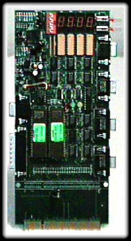 Pictured
here is a System Test board that I bought at World of Atari '98 show in Las
Vegas.
Pictured
here is a System Test board that I bought at World of Atari '98 show in Las
Vegas.
I don't know if this was used specifically by Atari or if IBM used it too during Jaguar manufacturing.
This board plugs into a Jaguar unit. Has connections to connect to the joystick ports, DSP port, and video port (not sure on the video port yet). The program contained in the ROMs runs through various system tests to test a Jaguar for proper functionality.
This is similar type of diagnostic hardware that Atari used on the 8-bit computers and 2600/5200/7800 consoles for repair. You would connect a device like this to the computer/console and run various video, memory, I/O tests.
Update (16 Jan 01) - I recently acquired documents and schematics for the system test board. The connectors for the board are as follows, starting with the upper right connector and going clockwise:
9-pin female - RS232 terminal cable (connects to the serial port of a PC)
9-pin male - DSP loop back (connects to the DSP port on the Jaguar under test)
High-density 15 pin - Joystick port 1 loop back (connects to Jaguar)
High-density 15 pin - Joystick port 0 loop back (connects to Jaguar)
25-pin male - Video loop back (connects to video port on the Jaguar under test)
High-density 15 pin - Video out (optional)
Two RCA audio connectors - not on board (optional)
There are two switches on the upper right of the board. The top switch is used to select tests to perform and the one below it is a reset switch.
The RS232 connector is connected to a PC using a simple 9pin to 9pin or 9pin to 25pin serial cable. Just connect pin 2 to pin 2, pin 3 to pin 3, and pin 5 to pin 5 for a 9pin to 9pin cable. For a 9pin to 25pin, pins 2 and 3 connect the same, but connect pin 5 (9pin) to pin 7 (25pin). Operate the PC serial port with the following settings: 9600 baud, 8bits, no parity, 1 stop bit, and XON/XOFF handshaking.
Since I found this information, I've been able to successfully connect my PC to the Jaguar test board. Click here to see a capture of the text menus that were available.
The following links are to the schematics for the board. The JTC schematic has the information regarding the connectors on the board that will help me build the cables used for testing.
Jaguar test cartridge schematic, audio in circuit, and overall board layout
Also found was test procedure documents on the procedures Atari followed in using this test fixture. It appears to me that this was used to do the refurbished Jaguar testing. They used multisystem TV's with this board to check the NTSC and PAL signal output abilities of Jaguar's. Click here to view a on-line viewable version of the test procedure.
And last but not least, information on the dip switches used on the board to configure the test unit for attended / unattended testing and/or enable / disable of various tests. Below is a table of showing the various settings:
| 0 = DIP switch ON or switch CLOSED | ||||||||
| 1 = DIP switch OFF or switch OPEN | ||||||||
| x = Don't care | ||||||||
|
S1
|
S2
|
S3
|
S4
|
S5
|
S6
|
S7
|
S8
|
|
|
1
|
x
|
x
|
x
|
x
|
x
|
0
|
x
|
Switch 1 always OFF, 7 ON |
|
1
|
1
|
x
|
x
|
x
|
x
|
0
|
x
|
Run selected tests once only |
|
1
|
0
|
x
|
x
|
x
|
x
|
0
|
x
|
Repeat selected tests forever |
|
1
|
x
|
0
|
x
|
x
|
x
|
0
|
x
|
Run Full Unattended Test |
|
1
|
x
|
1
|
x
|
x
|
x
|
0
|
x
|
Run Full Attended Test |
|
1
|
x
|
x
|
0
|
x
|
x
|
0
|
x
|
Disable analog joystick test |
|
1
|
x
|
x
|
x
|
0
|
x
|
0
|
x
|
Disable analog audio tests |
|
1
|
x
|
x
|
x
|
x
|
0
|
0
|
x
|
Disable PLL test |
